CASE STUDY ON DATA CENTER
DATA CENTER:
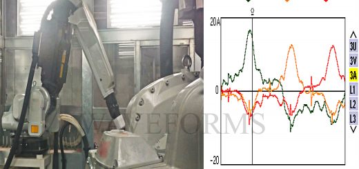
Equipment Used: Power Quality Analyser CHAUVIN ARNOUX Model no CA 8332 B Serial No: 306627.
Data center electrical power costs is not normally effectively managed due to improper placement of ups, wrong choice of cooling equipments, choosing of poor power quality UPS, & inappropriate choice of power conditioners. In today’s environment, it is good public policy and good business to consider the options to control data center energy consumption. Recent articles suggest that for some customers the cost of electricity is greater than the cost of IT hardware. Many companies are beginning to consider the carbon consumption of their ongoing operations and realizing that data centers are significant contributors to the environmental burden of business and industry.
In this paper, we will focus on the power consumption and efficiency of data center power and harmonics mitigation, which consumes 50% or more of the electrical power in a typical installation.
we will use Power Usage Effectiveness (PUE) as the metric for measuring data center physical infrastructure efficiency. PUE is expressed as the ratio of total data center input power to IT load power. Lower PUE means less energy “overhead” is consumed in powering the IT load, which means higher electrical efficiency for the data center. A PUE of 1 would indicate no energy overhead and perfect efficiency, which would mean the only power needed to support the IT load is the power actually consumed by the IT load. If the data center were perfectly efficient, all the power supplied to the data center would reach the IT loads – this is the ideal case. In the real world there are a number of ways that electrical energy is consumed by devices other than the IT loads – for example, transformers, UPS, distribution wiring, fans, air conditioners, pumps, humidifiers, and lighting. Some of these devices, such as UPS and transformers, are in the power path that supplies power to the IT loads. Other devices, such as cooling and lighting, provide secondary support and protection, but do not supply power to the IT loads.
HARMONICS DATA SUMMARY OF DATA CENTER:
UPS 1 EB SUPPLY:
| RMS I | RMS V | KW | KVA | KVAR | PF | THD I | THD V |
| AVG 16 A | 233 V | 10.98 KW | 11.22 KVA | -1.844 KVAR | 0.97 | 18.49 % | 1.36 % |
| MIN 15 A | 232 V | 10.87 KW | 11.14 KVA | -3.11 KVAR | 0.96 | 14.10 % | 1.10 % |
| MAX 17 A | 234 V | 11.11 KW | 11.36 KVA | 720.1 VAR | 0.98 | 22.80 % | 1.60 % |
HARMONICS I: 3RD 16 % 5TH 10.50 % 7TH 12.30 % 9TH 5.70 % 11TH11.60% 13TH 9.2%
UPS 1 DG SUPPLY:
| RMS I | RMS V | KW | KVA | KVAR | PF | THD I | THD V |
| AVG 16 A | 234 V | 11.31 KW | 11.47 KVA | -1.844 KVAR | 0.98 | 15.37 % | 1.41 % |
| MIN 16 A | 233 V | 11.03 KW | 11.20 KVA | -2.134 KVAR | 0.98 | 12 % | 1.10 % |
| MAX 18 A | 235 V | 12.07 KW | 12.25 KVA | -428.9 VAR | 0.98 | 19.50 % | 1.70 % |
HARMONICS I: 3RD 15.70 % 5TH 8.30 % 7TH 8.8% 9TH 4.4% 11TH6.5% 13TH 2.6%
UPS 1 OUTPUT:
| RMS I | RMS V | KW | KVA | KVAR | PF | THD I | THD V |
| AVG 15 A | 229 V | 9.008 KW | 9.334 KVA | -2.118 KVAR | 0.96 | 10.50 % | 0.71 % |
| MIN 15 A | 229 V | 8.981 KW | 9.304 KVA | -2.133 KVAR | 0.96 | 9.90 % | 0.60 % |
| MAX 15 A | 230 V | 9.029 KW | 9.357 KVA | -2.102 VAR | 0.96 | 10.20 % | 0.80 % |
HARMONICS I: 3RD 3.7% 5TH 8.40% 7TH 4.30% 9TH 1.3% 11TH 1.7% 13TH 1.5%
UPS 2 EB SUPPLY:
| RMS I | RMS V | KW | KVA | KVAR | PF | THD I | THD V |
| AVG 16 A | 235 V | 11.05 KW | 11.45 KVA | -2.878 KVAR | 0.96 | 20.70 % | 2.00 % |
| MIN 15 A | 233 V | 10.92 KW | 11.27 KVA | -3.940 KVAR | 0.94 | 20.60 % | 1.70 % |
| MAX 17 A | 237 V | 11.19 KW | 11.68 KVA | 745.6 VAR | 0.98 | 18.50 % | 1.80 % |
HARMONICS I: 3RD 14.30% 5TH 10% 7TH 9.6% 9TH 7.8% 11TH 10.20% 13TH 8.5%
UPS 2 DG SUPPLY:
| RMS I | RMS V | KW | KVA | KVAR | PF | THD I | THD V |
| AVG 16 A | 234 V | 11.11 KW | 11.50 KVA | -2.937 KVAR | 0.96 | 23.10 % | 1.80 % |
| MIN 16 A | 234 V | 11.00 KW | 11.31 KVA | -3.852 KVAR | 0.94 | 21.30 % | 1.30 % |
| MAX 17 A | 234 V | 11.21 KW | 11.69 KVA | -1.901 KVAR | 0.98 | 19.20 % | 1.40 % |
HARMONICS I: 3RD 18.60 % 5TH 8 % 7TH 9.9% 9TH 6.1% 11TH6.6% 13TH 4.6%
UPS 2 OUTPUT:
| RMS I | RMS V | KW | KVA | KVAR | PF | THD I | THD V |
| AVG 18 A | 231 V | 9.302 KW | 10.08 KVA | -2.291 KVAR | 0.92 | 14.99 % | 1.00 % |
| MIN 18 A | 231 V | 9.247 KW | 10.03 KVA | -2.309 KVAR | 0.92 | 11.50 % | 0.70 % |
| MAX 19 A | 231 V | 9.380 KW | 10.17 KVA | -2.276 VAR | 0.92 | 9.30 % | 1.10 % |
HARMONICS I: 3RD 9.7% 5TH 11.90% 7TH 8.30% 9TH 3.7% 11TH 4.7% 13TH 2.30%
UPS 3 EB SUPPLY:
| RMS I | RMS V | KW | KVA | KVAR | PF | THD I | THD V |
| AVG 27 A | 235 V | 20.00 KW | 20.28 KVA | -3.061 KVAR | 0.98 | 10.18 % | 1.70 % |
| MIN 26 A | 233 V | 19.41 KW | 19.73 KVA | -4.457 KVAR | 0.97 | 7.7 % | 1.50 % |
| MAX 29 A | 237 V | 21.42 KW | 21.69 KVA | -93.07 VAR | 0.98 | 12.50 % | 1.70 % |
HARMONICS I: 3RD 8.60 % 5TH 4.60% 7TH 7.9% 9TH 3.6% 11TH 5.7% 13TH 4.5%
UPS 2 DG SUPPLY:
| RMS I | RMS V | KW | KVA | KVAR | PF | THD I | THD V |
| AVG 29 A | 234 V | 21.11 KW | 21.39 KVA | -1.621 KVAR | 0.98 | 11.70 % | 1.60 % |
| MIN 28 A | 234 V | 20.00 KW | 20.26 KVA | -4.172 KVAR | 0.97 | 12.50 % | 1.30 % |
| MAX 37 A | 234 V | 26.71 KW | 26.99 KVA | – 112.5 VAR | 0.99 | 12.10 % | 1.50 % |
HARMONICS I: 3RD 9.60 % 5TH 5.60 % 7TH 6.10% 9TH 4.40% 11TH 3.80% 13TH 4.30%
UPS 3 OUTPUT:
| RMS I | RMS V | KW | KVA | KVAR | PF | THD I | THD V |
| AVG 34 A | 229 V | 16.74 KW | 23.39 KVA | -16.20 KVAR | 0.71 | 72.50 % | 1.40 % |
| MIN 34 A | 229 V | 16.51 KW | 23.15 KVA | -16.29 KVAR | 0.71 | 85.10 % | 1.50 % |
| MAX 37 A | 229 V | 17.56 KW | 24.01 KVA | -16.10 KVAR | 0.73 | 78.10 % | 1.40 % |
HARMONICS I: 3RD 62.20 % 5TH 44.90% 7TH 30.70% 9TH 18.30% 11TH 7.40% 13TH 3.40%
UPS 1 ISOLATION TRANSFORMER:
| RMS I | RMS V | KW | KVA | KVAR | PF | THD I | THD V |
| AVG 12 A | 231 V | 4.20 KW | 4.56 KVA | -1.784 KVAR | 0.91 | 15.40 % | 0.90 % |
| MIN 12 A | 231 V | 4.16 KW | 4.53 KVA | -1.812 KVAR | 0.91 | 16.20 % | 0.9% |
| MAX 12 A | 231 V | 4.29 KW | 4.66 KVA | -1.769 KVAR | 0.91 | 26.80 % | 1.10 % |
HARMONICS I: 3RD 23.30 % 5TH 6.30% 7TH 5.5% 9TH 2.4% 11TH 2.8% 13TH 3.8%
UPS 2 ISOLATION TRANSFORMER:
| RMS I | RMS V | KW | KVA | KVAR | PF | THD I | THD V |
| AVG 15 A | 234 V | 3.824 KW | 4.370 KVA | -2.074 KVAR | 0.55 | 13.60 % | 0.6 % |
| MIN 15 A | 234 V | 3.812 KW | 4.359 KVA | -2.080 KVAR | 0.55 | 0 % | 1.0 % |
| MAX 15 A | 234 V | 3.852 KW | 4.398 KVA | – 2071 VAR | 0.55 | 12 % | 0.7 % |
HARMONICS I: 3RD 11 % 5TH 2.7 % 7TH 1.3% 9TH 2.8%
AC:
| RMS I | RMS V | KW | KVA | KVAR | PF | THD I | THD V |
| AVG 23 A | 236 V | 11.87 KW | 13.43 KVA | 6.237 KVAR | 0.88 | 14.80 % | 1.60 % |
| MIN 23 A | 235 V | 11.80 KW | 13.33 KVA | 6.167 KVAR | 0.88 | 13.90 % | 1.40 % |
| MAX 23 A | 236 V | 11.91 KW | 13.48 KVA | 6.297 KVAR | 0.88 | 17.70 % | 1.40 % |
HARMONICS I: 3RD 8.4 % 5TH 11.50% 7TH 7.90% 9TH 2.20% 11TH 4.50% 13TH 2.5%
EARTH RESISTANCE TEST FOR EARTH ELECTRODES:
System body earth electrode BE1 Less than 3 ohms
System body earth electrode BE2 Less than 3 Ohms
UPS neutral earth electrode NE1 Less than 3 Ohms
UP neutral earth electrode NE2 Less than 3 Ohms
DATA ANALYSIS AND OBSERVATION OF DATA CENTER:
The primary loads of the Data centre are 1. UPS 2. Air-conditioning. The UPS constitute about 80% percentage of the total load, with lighting being marginal our focus is on UPS and Air-conditioning.
UPS: The UPS is oversized and hence the Power usage effectiveness (PUE) is high. The PUE is the metric used to measure the efficiency of the ups i.e) Input KW/Output KW. Since the 3nos of 80 KVA UPS is oversized by 50% and as the efficiency of the UPS increases with a minimum of 50% load. This is because the UPS no load current, smaller the UPS lower the no load current. The ideal sizing of UPS will be in the range of 40 – 50 KVA. Calculation on Power losses.
When ups @ 20% of load total loss will be 4.340KW
Annual loss will be Rs 97,000/-(approximate) for one UPS.
For three UPS system
Annual loss will be Rs 2,91,000/- (approximate)
The other important electrical parameters for measuring efficiency area a. efficiency b. Total Harmonic Distortion both at input and output of voltage (THDV)and current (THDI)and c. Power factor.
The IEE-519 standards are the bench marks for an ideal and efficient standards are as follows: Actuals readings are find above tables
Voltage THD at input: 5%
Current THD at input: 10%
Voltage THD at output 3%
Current THD at output 8%
However, from the data we find the following:
We observed that the 3rd harmonics as the dominant (16%), the 3rd harmonics are the most harmful and additive to the neutral. However, as the load is just about 20% of the total capacity of the UPS, as of now is not a serious concern as the 3rd harmonics can heat up the electrical system.
Isolation TransformerK-20 4 no’s of 100KVA is also oversized and beyond comprehension considering the load requirements. The Isolation Transformer with a delta primary and zig zag secondary could be a better and effective option for reduction of harmonics generated by the SMPS of the servers, as it could be effective in reducing the heat by 23% and improving efficiency, durability and reliability of SMPS which is very important of for critical mission operations. The power Loss caused by oversizing is enclosed.
Total losses will be 7.67KW @ full load condition
Yearly losses will be
7.67KW x 24Hrs x 365 days x Rs 6.35/- = Rs 4,26,651.42/- (approximate calculation for yearly basis)
Total loss @ 20 % load will be 1.534 KW
Yearly losses will be
1.534 KW x 24Hrs x 365 days x Rs 6.35/- = Rs 85,330.284/- (approximate calculation on yearly basis) for one isolation transformer
For four isolation transformer
Annual loss will be Rs 3,41,321.136/- (approximately)
We are just calculated the electrical power losses of UPS and Isolation transformer, and we have not ventured in to the cost of investment, Return On Investment, extra space requirements, cost of ownership (running cost and high cost of AMC). The total PUE should also include the extra air-conditioning Units required due to oversizing and consequently extra cooling requirements as data is not available.
However, for total PUE of data centres these calculations they will have to be considered. PUE is always a function of IT load – efficiency degrades at lower loads (refer to PUE graph)
Air conditioning: The performance of 3nos 15KW air-conditioning (Emerson digital scroll compressor) is very good and hence we have no adverse comments.
LOSS ESTIMATION:
TOTAL LOSS = TOTAL UPS LOSSES + TOTAL ISOLATION TRANSFORMER LOSSES
T L = Rs 2,91,000/- + Rs 3,41,321.136-
TOTAL LOSS = Rs 6,32,321.136/- (approximately for yearly basis)
Ideal green power solution with harmonics mitigation transformer
K-FACTOR TRANSFORMER vs HARMONIC MITIGATING TRANSFORMER:
A K-Factor transformer can be auto-wound, double wound, single phase or three phase. It is simply one that is designed to withstand the effects of harmonic rich loads currents without overheating. In basic terms, the higher the K-Factor, the greater the level of harmonic load current that the transformer is able to handle.
To achieve a cost effective solution, the design of a K-Factor transformer not only allows capacity to accommodate the self-heating effects due to the harmonic currents, principally within the conductors of the transformer, but also seeks to minimise that heating by the choice of winding conductors and their arrangement.
A harmonic mitigating Transformer (HMT) not only uses the techniques employed in the K-Factor transformer but goes further by the use of winding arrangement and or connection to bring about the cancellation or mitigation of some of the effects of the harmonic currents. To do this requires the use of more than one phase current and so HMT’s are usually three phase.
One of the major weaknesses of the three phase K-Factor transformer, which is typically a delta primary to star secondary, is that where triplen harmonics are present they appear in the primary delta winding as a circulating current proportional to the balanced portion of the triplen harmonics.
Some suggestions:
- The present configuration does not have a redundancy, Maintenance shut down becomes difficult. Failure of one UPS means risk of reduced reliability of the data centre.
- THD V and current both at input and output kept to IEE-519 standards are critical for selecting a UPS. High Harmonics degrades the efficiency and reliability of the Data centre. Conformance to IEE-519 standards is important.
- Usage of the right Harmonic mitigating transformers are important for power Quality, reliability and efficiency.
ADVERSE EFFECTS OF TRIPLEN HARMONICS:
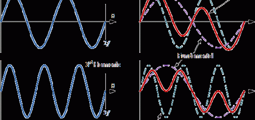
The instantaneous sum of the currents in the three phases taken at any moment will also be zero if the linear loads are perfectly balanced. If they are not, then there will be a small residual neutral current as shown. With linear loads, the neutral conductor can be the same size as the phase conductors because the neutral current will not be larger than the highest phase current. Unfortunately, this is definitely not true for non-linear phase-to-neutral loads. 220VAC non-linear loads like the SMPS used in computers and in monitors draw current in two distinct pulses per cycle. Because each pulse is narrow (less than 60 degrees), the currents in the second and third phases are zero when the current pulse is occurring in the first phase. Hence no cancellation can occur in the neutral conductor and each pulse of current on a phase becomes a pulse of current on the neutral.
Even if the phase currents of the SMPS loads are perfectly balanced in RMS amperes, the RMS value of the neutral current can be as much as √3 times the RMS value of the phase current because there are 3 times as many pulses of current in the neutral than in any one phase. If the phase current pulses do overlap because they exceed 60 degrees in width, then there will be some cancellation so that the neutral current will be less than √3 times the phase current. Overlapped or not, because there are 3 times as many pulses in the neutral than in a phase, the predominant component of the neutral current will be the 3rd harmonic (150Hz for a 50Hz system). This is evident in the waveforms of Figure since the linear current completes only 2 cycles in the same time period that the non-linear neutral current completes 6 cycles or 3 times the fundamental.
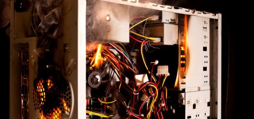
Triplen harmonics are of the zero sequence unlike the fundamental which is positive, the magnitude of the currents of these harmonics on a 3-phase system is additive in the neutral circuit. This can cause very large currents to flow in the neutral, and unless the neutral is sufficiently oversized to handle the extra current, significant heating can occur causing a fire hazard.
ABOUT US:
WAVEFORMS commenced its manufacturing operation in December 1989. Since its inception it specialized in power electronics products like UPS, battery chargers, power supplies. We subsequently diversified into power quality products from the year 2005. We conduct power quality studies and analyse data collected in real-time and providing accurate, ideal, cost effective, reliable, robust & durable solution for electrical infrastructure.
WAVEFORMS conducted more than 500 Power quality Audits for HT/LT industries and provided Solutions to many of them, including implementation. Some of the industries include, Data centres, Automobile, Textile, Plastic, Paper, pharmaceuticals and other process industries. Our experience and expertise gives us the edge in providing simple, innovative, ideal, durable, robust and cost effective solutions.
WAVEFORMS has been consistently delivering world class products that are preferred by many customers over three decades.
We are also offering the following product & services that will give you the edge and distinct advantage and therefore be competitive in a world of intense competition.
Our Products Profile
- Power Quality( Advance Universal Harmonic Passive Filter, Line Reactor, Sine Wave Reactor & ZigZag Reactor )
- Harmonics Mitigating Transformer (Single Output HMT, Dual Output HMT & Neutral Harmonics Eliminator)
- Power Usageeffectiveness in Data Center
- Power Factor Correction ( Automatic Power Factor Correction, Detuned Power Factor Correction & Dynamic power factor correction )
- Industrial LED Lighting Solution
- Power Conditioning (Socomec UPS, Constant Voltage Transformer, Servo Stabilizer & Home Inverter )
Our Services
We recommend innovative, ideal, durable, robust and cost effective solutions to improve your power quality,reliability and efficiency.
Please feel free to call or mail us.
MAIL ID à waveformspower@gmail.com
WEBSITE à https://www.waveforms.co.in/